(Please scroll to the bottom of this page to access the menu)


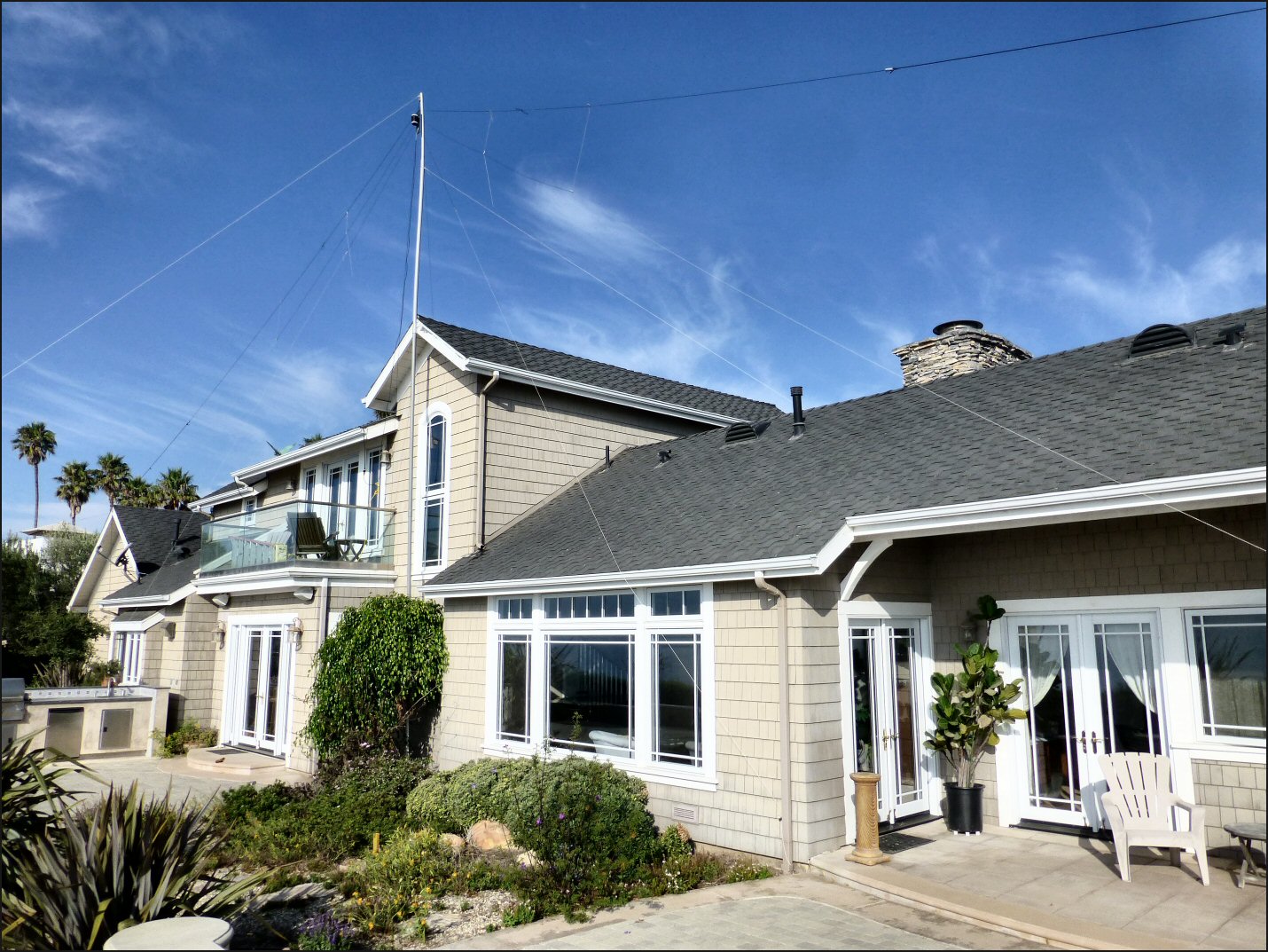
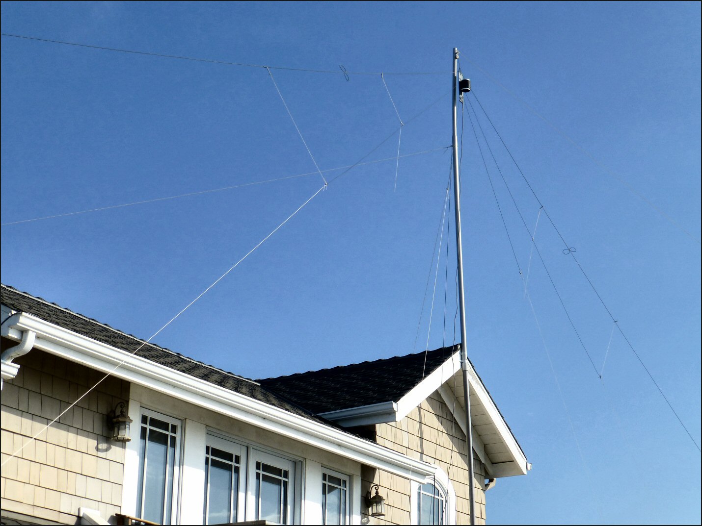
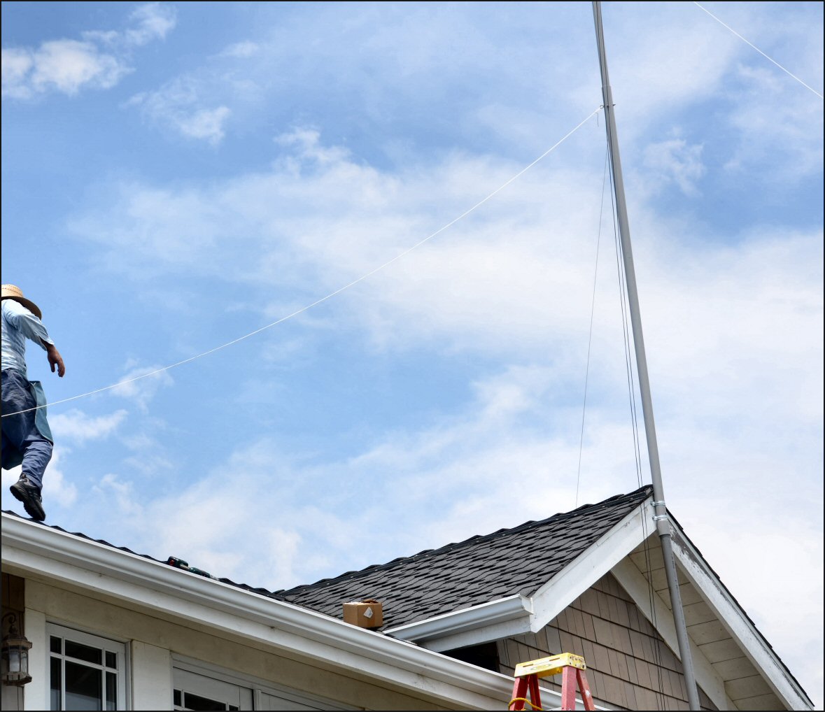
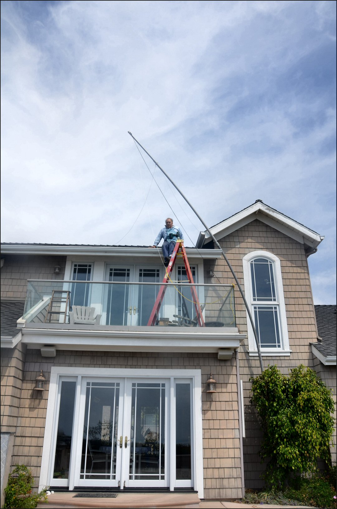
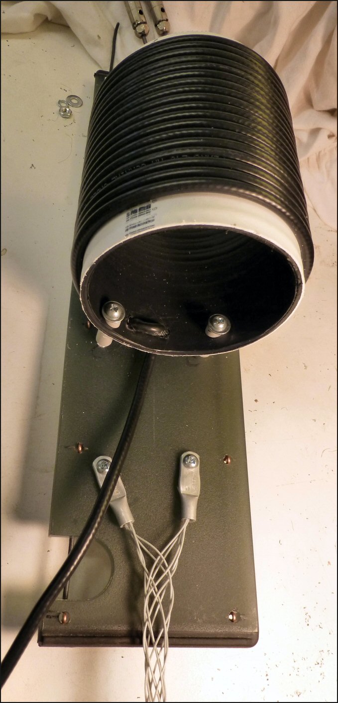
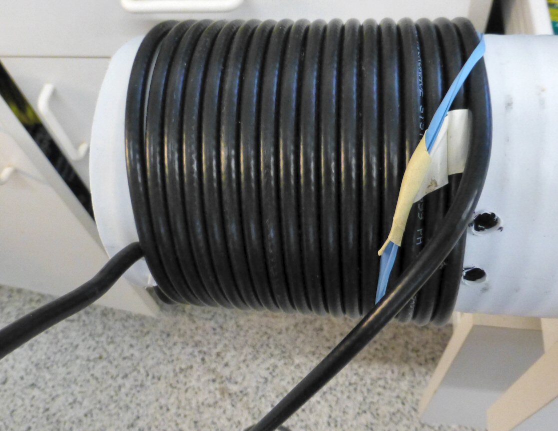
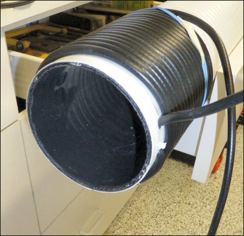
Five-Band Parallel Half-Wave Dipole Antenna

This antenna was constructed as an expedient to enable station operation within a week of receiving FCC license certificate. 
It is easily lowered for tuning and maintenance with the three Dacron lines attached at the midpoint and ends.  It's construction has been effective in providing hands-on experience in the behavior of radio frequency currents and suitable crafting techniques.  Its design is a distillation of many publications and on-line documents summarized in these notes.  The forty-meter element at the top is able to resonate within the fifteen-meter band by virtue of its third harmonic augmented with two figure-eight capacitance-hats to lower its characteristic resonance on fifteen-meters.  An effective one-to-one current balun is fabricated with eighteen turns of LM-250 coaxial cable wound on a four inch plastic pipe form to suppress common-mode currents from traveling down the feed line.  Short lengths of PEX tubing attached to nylon twine are used as end and suspension insulators for the lower twenty-meter and ten-meter elements.  The mast rises fifteen feet above the twenty foot high roof peak at the apex.  The ends are sixteen feet above the ground, with the intention of lowering the dipole's characteristic seventy-five ohm impedance toward the fifty ohm coaxial feed line impedance.  Measurements indicate that may not have been necessary, and increasing the height of the ends may be done at some time in the future.  A small heat-gun has proven effective in sealing the ends of the Dacron lines, and cutting the nylon twine to prevent them from unraveling.  The mast is ten feet of two inch schedule eighty PVC conduit sleeved over a five foot piece of inch and a half schedule forty PVC pipe, and supported by three white Dacron lines.  The lower two ten foot lengths of PVC pipe are intended to be temporary support for erecting the mast, and may be removed.  All exposed connections and wire element ends are coated with liquid tape to prevent corrosion and contamination. 


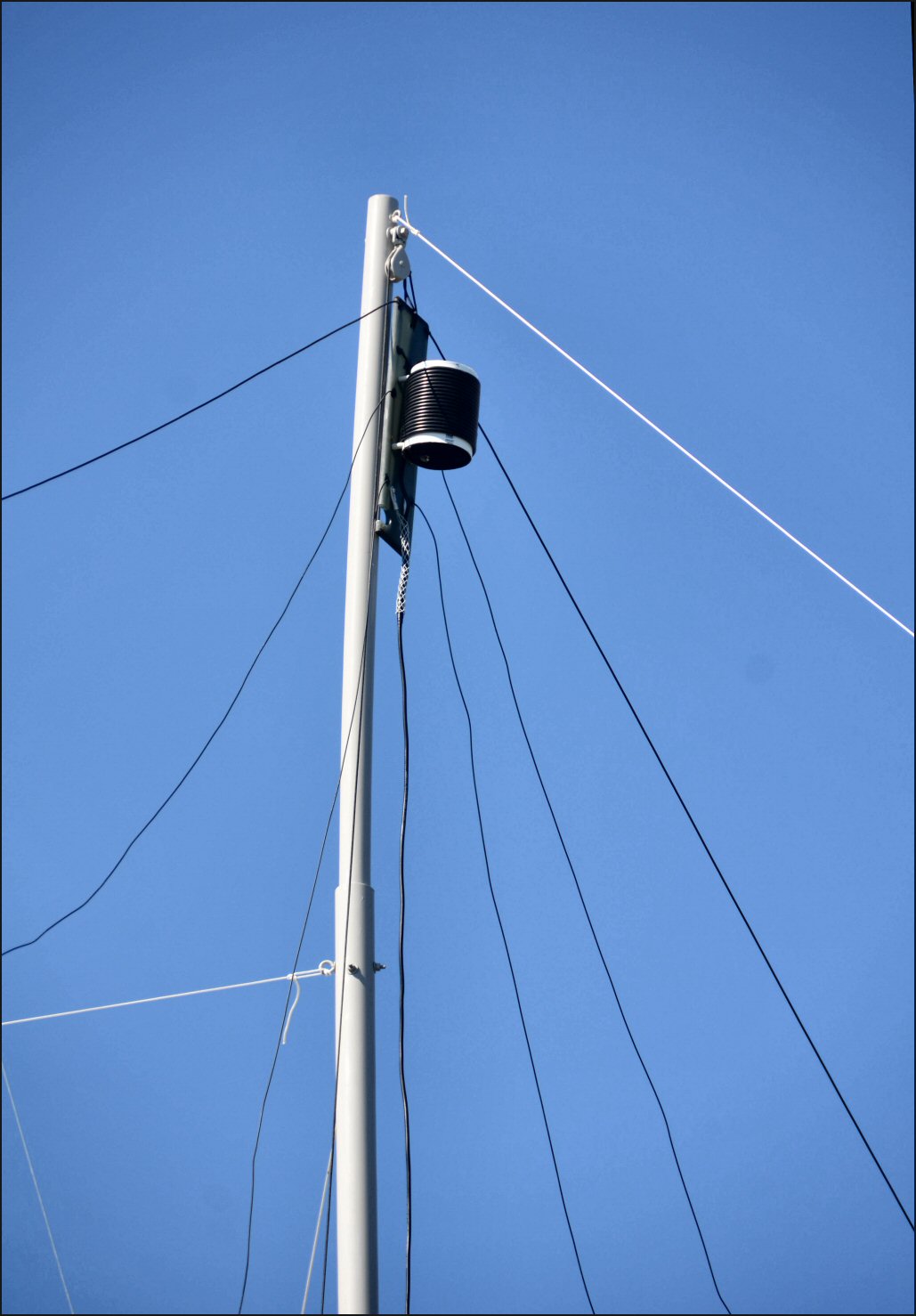
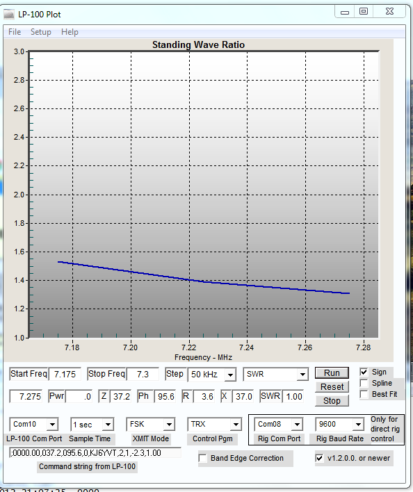
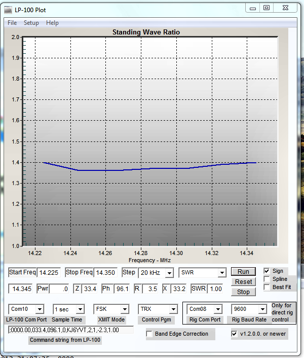
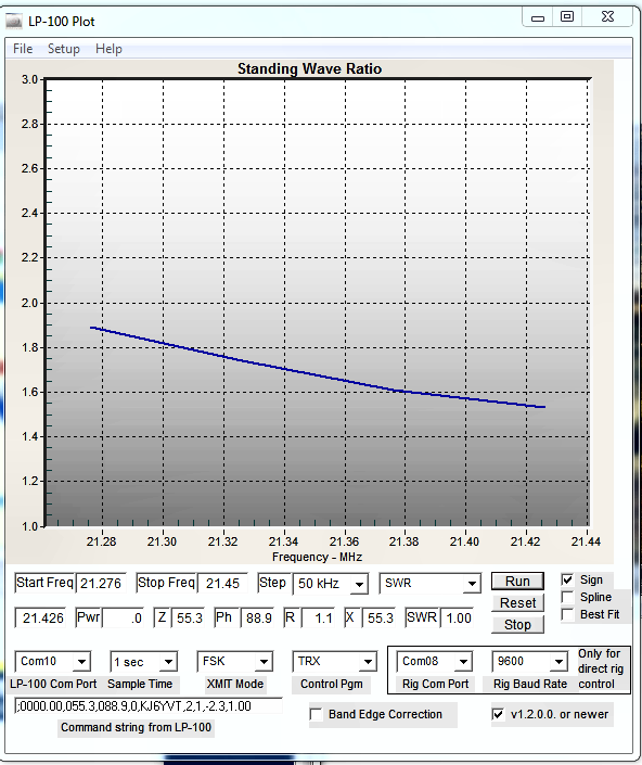
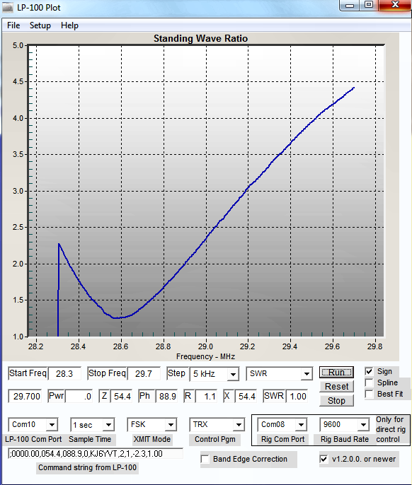
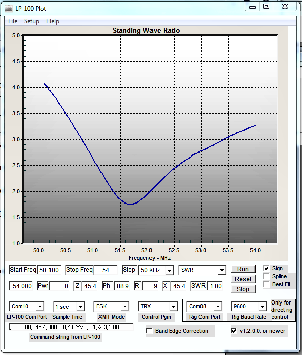
Below are SWR plots for the five bands this parallel dipole is resonant.  SWR is below 1.5:1 for the 40-meter and 20-meter elements.  The resonant point of the 3rd harmonic of the 40-meter element has been shifted lower through the installation of capacitance-hats resulting in the SWR being below 2.0:1.  The comparatively high Q of the single-wire dipole results in a rather narrow bandwidth of the 10-meter element, but SWR is below 2.5:1 from the low end of the 10-meter band to about 29 MHz.  Interestingly enough, the 7th harmonic of the 40-meter element resonates near 51.7 MHz permitting operation from 50.125 MHz to 54 MHz with an SWR of 4:1 or less; the transceiver's internal antenna tuner seems to compensate for the high SWR quite well.

The plots below were generated with Larry Phipps' (N8LP) LP-11 Plot program that works in conjunction with his LP-100A digital vector RF wattmeter.


[an error occurred while processing this directive]

 
 Home
 
 Station Construction
 
 Antennas
 
 Radios
 
 Amplifier
 
 Computer Automation


Back to top of page


 Butternut HF9V 80-6 Meter 9-Band Vertical
 
 Hex-Beam
 
 Remote Antenna Selector
 
 Remote Antenna Relay Box


Send e-mail to: KJ6YVT


Hits: [an error occurred while processing this directive] Date of last edit: June 04, 2013 14:01:55 -0700
© Copyright: L. Dighera, 2012; All Rights Reserved: LDighera@att.net