|
|
|||||||||||||||||||||||||||||||||||||||||||||||||||||||||||||||||||||||||||||||||||||||||||||||||||||||||||||||||||||||||||||||||||||||||||||||||||||||||||||||||||||||||||||||||||||||||||||||||||||||||||||||||||||||||||||||||||||||||||||||||||||||||||||||||||||||||||||||||||||||||||||||||


| KIO Broadband Hexagonal Beam Antenna
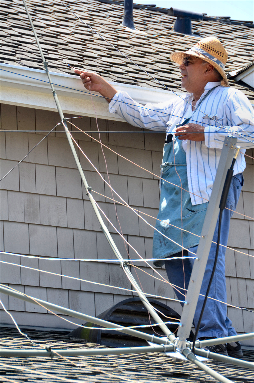
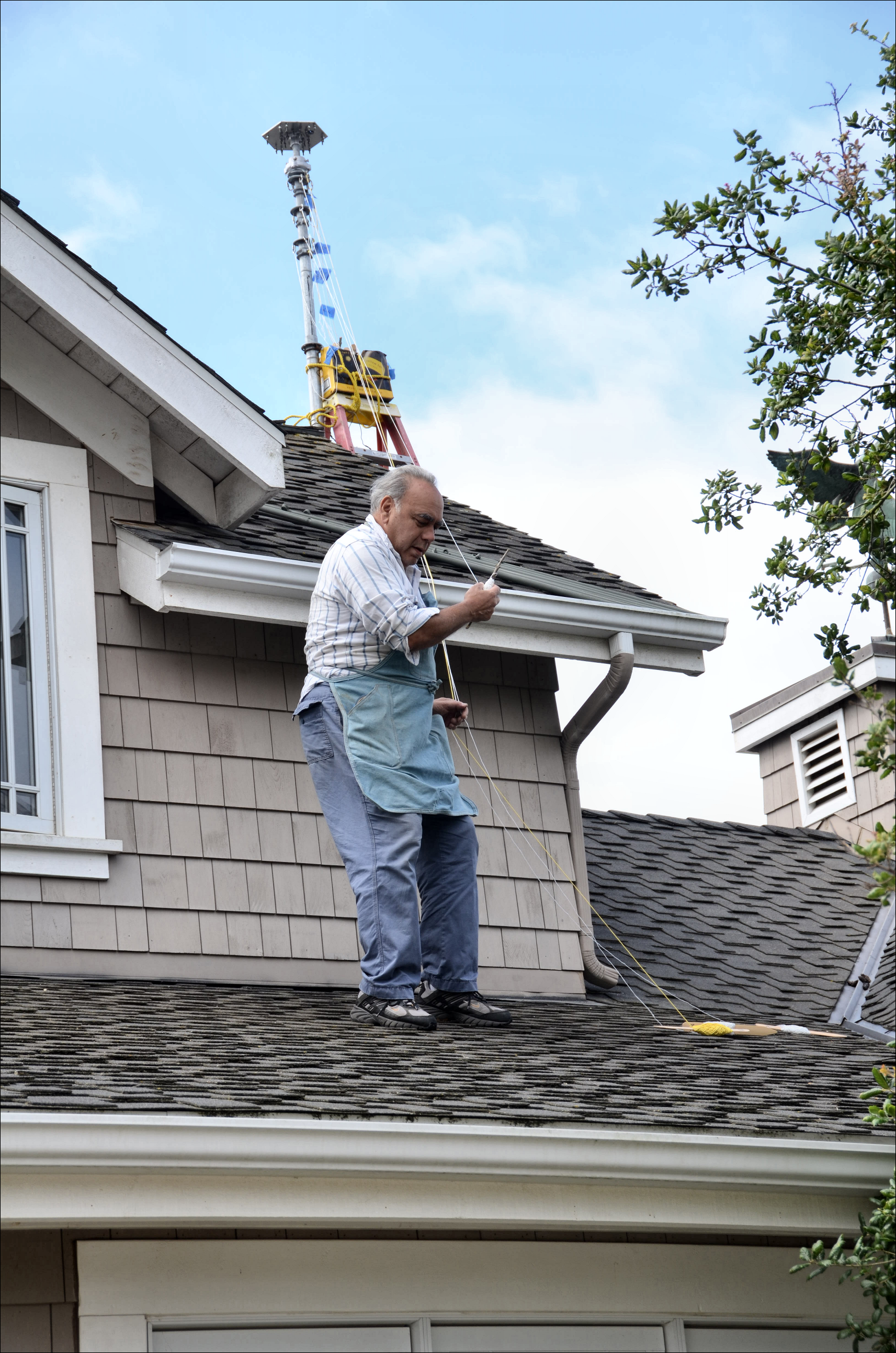
This two element, five band, directional antenna installation was accomplished in the following phases: 1. Plan installation location It was a bit of an ordeal for a 70 year old senior citizen to finally wrestle the ungainly maze of wires and poles that demand to catch on every composite roof shingle and other edges as I transported the KIO Hex-Beam from atop the first floor rooftop, where it was assembled, around dormers and weathervane, up steep rooftop and a ten foot ladder lashed to the mast. From there it was a matter of supporting myself with one arm wrapped around the top of the mast, and the other arm hefting the antenna's balancing mass to the tippy-top of the mast, and coaxing the hub and tube to mate. Whew! In my eagerness to mount the antenna in place, I skipped a few things like rubber-wrapping the top coax feed connector and 90 degree, testing for shorts/opens, connecting an antenna analyzer, etc.... Fortunately, after finally grounding the Alpha Delta coax surge suppressor, I just selected antenna five for the first time, and sent a short test transmission on each band: 6, 10, 15, 17, and 20 meters; all SWRs <3:1 with most in the 2:1 area over the majority of the band (plots below). I got lucky for a change. |
||||||||

Frame and support ropes |

Stringing 6-meter elements |

6-meter elements |

Stringing 17-meter elements |
|||||

Stringing 17-meter elements |
Threading 17-meter elements in P-clip |

Stringing 20-meter Elements |

Connecting the surge suppressor |
|||||

Mount, rotator, mast, antenna |

Hex-Beam looking at reflector elements |

Hex-Beam looking toward driven elements |

Hex-Beam looking toward driven elements |
|||||

Hex-Beam as seen from street |

Hex-Beam joins vertical and dipole |

20-Meter SWR Plot @ 20' AGL |

17-Meter SWR Plot @ 20' AGL |
|||||

15-Meter SWR Plot @ 20' AGL |
 10-Meter SWR Plot @ 20' AGL 10-Meter SWR Plot @ 20' AGL |
 6-Meter SWR Plot @ 20' AGL North 6-Meter SWR Plot @ 20' AGL North |
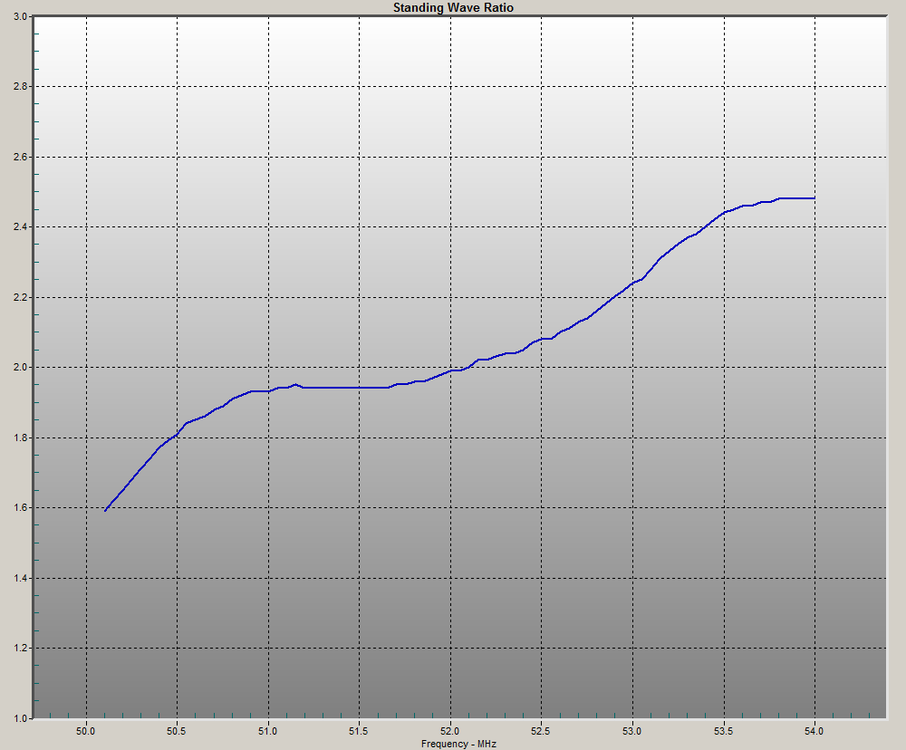 6-Meter SWR Plot @ 20' AGL South 6-Meter SWR Plot @ 20' AGL South |
|||||
| Rohn 9H50 34 Foot Push Up Mast | |||||||||

Mast, Hex-Beam base & thrust bearing |

Mast, Hex-Beam base & thrust bearing |

Guy ring bearings |
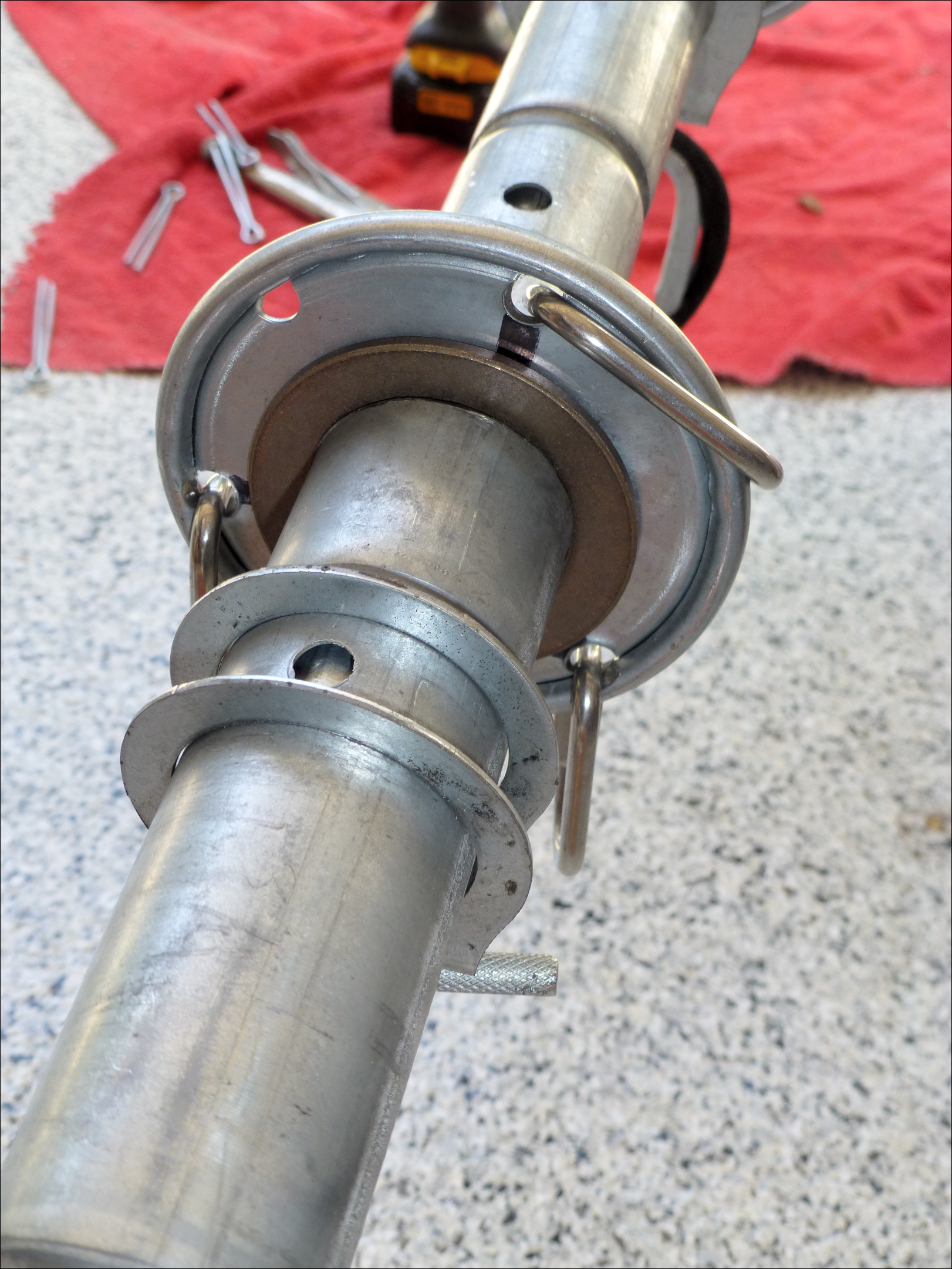
Guy ring bearing |

Mast butt filler |
|||||

Roof mount saddle layout |

Roof mount saddle layout |

Rotator and mast mounted |

Rotator and mast mounted |

Mast erected |
|||||

Ascending the 2nd story rooftop |

Ascending the 2nd story rooftop |

Preparing to attach guy measurement strings |

Preparing to attach guy measurement strings |
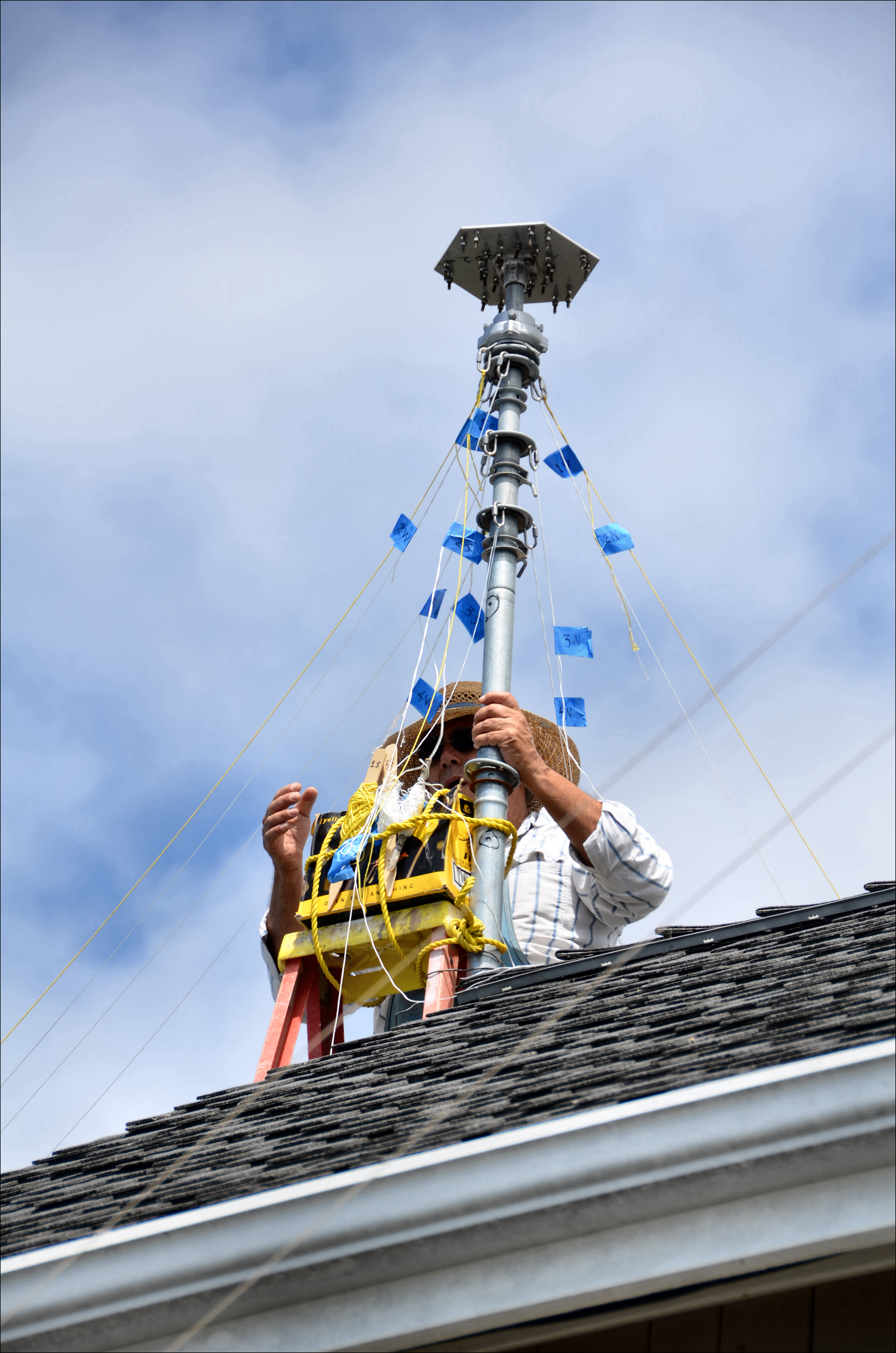
Attaching guy measurement strings |
|||||

Attaching guy measurement strings |

Extending 1st mast section |

Extending 2ndmast section |

Extending 3rd mast section |

Fully extended with strings |
|||||

Fully extended with strings |

Fully extended with strings |

Fully extended with strings |
Routing measurement strings toward guy anchor points |

Howdy |
|||||

Guy string measurement |

Cutting guy ropes to length of strings |

Coiling guy ropes |

Finished guy ropes cut to length |

Guy ropes and measuring string bobbins |
|||||
HARDWARE
I chose a Yeasu GS-050 Thrust Bearing mounted immediately under the antenna at the top of the mast. It has performed reliably in my maritime environment for eight years without the necessity of grease or other service.
I chose Double-braided Polyester Antenna Support Rope (Dacron equivalent) 5/16" 500ft - 1,790lbs strength $97.00, so no insulators are required to prevent guys from causing resonance issues.
Twelve ROHN 1/4 inch Standard Duty Open Eye Wire Rope Thimble R-1/4TH $1.14/each for attachment to the mast guy plates.
Three Crown Bolt 3/8 in. x 4-1/2 in. Zinc-Plated Lag Thread Screw Eyes $0.98 /each, that will be lagged into roof rafters.
Three Tight Rope--Antenna Rope Tightener Product Code: Buckmaster Line-Grip™ $7.00/each, available at Orchard Supply Hardware as 'Clothesline Tighteners' for less than half the price. My intent is to use these tope tighteners as temporary anchors while pushing up the mast and rigging the guy ropes, and then replacing them with rope hitch knots. I wouldn't trust them to stand up against the 70 knot winds that assault us here in the winter; they are very useful during the erection process to temporarily adjust
the guy rope length each time a mast section is extended.
Graphite impregnated bronze bearing washers were purchased from McMaster Carr on the advice of an article by Mike (K2MK) I found in the Yahoo hex-beam group in the Files section. I found that there is an issue in finding graphite bearing washers with the correct ID of the hole to snugly fit the mast on some sections, and they are not cheap. Here's what I purchased, but you can probably improve on my choices:

One 7447K31 Graphite SAE 841 Bronze Thrust Bearing,
for 1-1/2" Shaft Diameter, 2-1/2" OD, 1/8" Thick $5.10 Each.
Two 7447K33 Graphite SAE 841 Bronze Thrust Bearing,
for 1-3/4" Shaft Diameter, 2-5/8" OD, 1/8" Thick $4.90 Each.
Three 7447K34 Graphite SAE 841 Bronze Thrust Bearing,
for 2" Shaft Diameter, 3" OD, 1/8" Thick $5.93 Each.
I found this document useful in planning the installation.
![]()
Mast Section Dimensions are:
(1) 8' 2.25" length x 1.25" O.D. (16 AWG)
(2) 7' 10.5" length x 1.50" O.D. (18 AWG)
(3) 7' 04.5" length x 1.75" O.D. (18 AWG)
(4) 6' 10.5" length x 2.00" O.D. (18 AWG)
(5) 6' 04.5" length x 2.25" O.D. (18 AWG)
I found the stainless steel 'Quick Link' u-shaped pieces that the guy ropes are wrapped around where they terminate on the mast end most reasonably priced at Orchard Supply.
Yes. I used a Bowline knot on each end of the guy ropes to terminate them. You'll find information about the four knots I've
found useful with antenna work in the document here.
Where the K4KIO hexbeam flange plate mounts to the top 1-1/4 inch o.d. section of the mast I drilled-out one of the setscrews as
mentioned in the K4KIO instructions, and replaced it with a stainless steel 1/4 X 20 bolt and nylock nut. Later I found this junction to be critical for two reasons:
1. The top steel mast section is thin enough to be bent above the top guy point in a strong wind. I would suggest plugging it with a wooden dowl to stringthen it.
2. The hole drilled through the flange and top mast section needs to be a close fit to minimize it becoming enlarged during heavy wind conditions that will tend to repeatedly rotate the antenna in an oscillatory manner and deform the holes over time.
I used stainless steel clevis pins through holes drilled through the mast to pin the mast sections together, rather than the cotterpins and indents on the bottom of the mast sections. This will prevent the mast from potentially slipping out of the indentations and becoming disoriented/out of alignment in heavy winds.
NOTES
A note from Leo Shoemaker:
To: <Larry@KJ6YVT.com>
Subject: Hex Beam
From: "Leo Shoemaker" <lbsbhm@gmail.com>
Date: Sat, 27 Oct 2012 13:36:50 -0500
Larry, here is my suggestion for erecting the mast.
First, I assume that the first section is braced against something, a wall,
a post or some fixed structure that will allow you to climb a ladder with
the hex beam in one hand to carry it up to where you can put it on the
un-extended mast.
Get a pair of latex covered cloth gloves from Home Depot (cost = $6). They
are blue and white. These will protect your hands and also give you a much
better grip on the mast. Before putting the hex on the mast, extend the mast
without the antenna. Adjust the guy ropes when it is fully extended and
without the weight of the antenna. Also, with a black marker mark the holes
with a longitudinal line so that as you extend the mast later with the hex
on it you will know when you are approaching one of the holes on an inner
section for insertion of the pin. Now lower the mast and proceed with
installing the hex beam on it.
Now, when you are ready to actually install and raise the antenna, climb the
ladder holding the antenna with one hand by the center post at the balance
which is about 8 inches above the base plate. As you climb, simultaneously
raise the antenna into a vertical position holding it back over your
shoulder. Be careful that the spreader arms, cords and wires clear all
bushes, tree limbs, etc. They love to grab whatever is within 5 miles of
your site. Do not drop the antenna on its side as this will delay the entire
installation about a week while you contact me to buy a replacement spreader
arm. I promise you that if you drop the antenna on its side you WILL break a
spreader arm, maybe two. Do everything in slow motion, using the eyes in the
back of your head as well as the front.
Place the antenna on the mast. Drill the cross bolt hole in the bottom
flange and mast and install the cross bolt. Now, begin raising the mast
section until you reach the place to insert the first pin. If the first
section of the mast is braced against a post or wall, you should be able to
raise the antenna without the whole thing tilting over. Repeat this with the
next section and so on. You will thank me for the idea of marking the hole
locations with that longitudinal line. Those holes are so hard to find when
they are hidden by the larger section covering them until the inner section
is raised enough to expose them.
You will thank yourself for the good sense of mounting the rotator at the
bottom and not at the top as it took all you had to just get the fool
antenna up to say nothing of that added weight of the rotator. You see, it
is not the weight itself, the whole thing wants to tilt slightly while
raising it, greatly increasing the friction of the telescoping sections and
the friction increases exponentially with the increase in weight.
When raised to its final position, the guy ropes should be pretty close to
correct. Do not over tighten the guy ropes. Remember the tighter they are,
the greater the downward pressure making it hard to raise the antenna. Plus,
the downward pressure increases the possibility of the mast buckling when
wind hits it. Instead leave some slack in the guy ropes, like you did the
hex beam wires. Sure, the wind will cause the thing to sway a bit. But
that's ok. Better to sway and survive than to buckle.
Hope this is helpful and forgive the feeble attempts at humor. It is better
to keep a sense of humor than to have a heart attack.
73, Leo
PS:
A suggestion; extend the mast to its operating position without the antenna
weight on it in order to adjust all guy ropes. Then when you raise the antenna,
the guys will be already adjusted. Do not make them too taut as they produce a
downward pressure that makes raising the antenna that last few inches to put
the cotter pins in place, very tough. Plus they add to a tendency to buckle the
mmast in wind. Slack guys are better but not too slack of course.
|
https://www.yaesu.com/indexVS.cfm?cmd=DisplayProducts&ProdCatID=104&encProdID=9CD2145C24AE53C5A6C62D7D703A9F3C&DivisionID=65
|
Yaesu G-450A Antenna Rotator: The Yaesu G-450A Rotator is a light duty antenna rotator, featuring automatic slow start and stop, 450 degree rotation (allows a 90 degree overlap), overlap indication LED, and automatic brake release. The backlit analog control box features a round meter with a movable beam heading template. G-450A Technical Specifications: |
|||

 You can create an azimuthal world map card to assist in manually pointing your directional antenna with the free program/a> provided by Tom Epperly (NS6T).
Here are instructions on installation of the azimuthal card and ERC in the Yaesu G-450A Antenna Rotator
|
|
||||
|
|
||||
|
|
||||
|
|
|||||||||||||||||||||||||
| Hits: [an error occurred while processing this directive] | Date of last edit: September 5, 2020 16:22:25 -0800 | |||||||||||||||||||||||||
| © Copyright: L. Dighera, 2012; All Rights Reserved: LDighera@att.net | ||||||||||||||||||||||||||